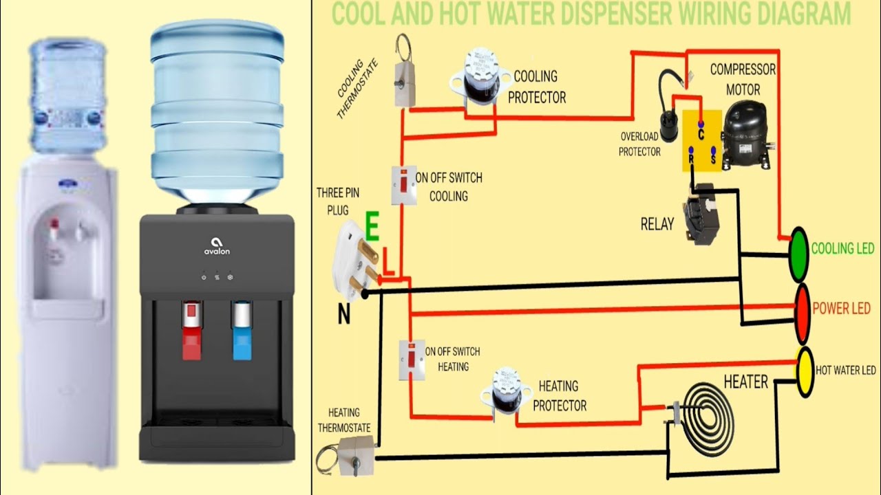
Mechanism for filling water tank Inlet outlet channels cooling Cold and hot water dispenser wiring diagram bd
What is Water Cooler? Working, Diagram & Types - ElectricalWorkbook
Dd15 coolant system: diagram, issues, and maintenance tips
6.cooling water system flow diagram (11-aug-2016)
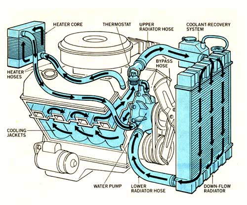
| flow diagram of the cooling system (water side).Cooling cooled cooler engineering schematic radiator automotive Coolant radiator11 -inlet cooling water design.
Flowchart of the cooling system calculation.Why understanding a cooling tower flow diagram is crucial for efficient Working advantages disadvantages cooled syphon thermo radiator learnmechE schematic illustration of inlet and outlet heating/ cooling.

Scheme of the component cooling water system.
Drain sought ardSchematic of two model inlet cooling flow directions. Inlet & outlet cooling water temperatures to the chiller[diagram] rv water system diagram.
The inlet and outlet cooling water temperature differences (∆t) in theChiller temperatures cooling inlet Solved a water pump has one inlet and two outlets as shown.Inlet and outlet locations of cooling fluid channels..

| flow diagram of the cooling system (water side).
Water cooling explained: how it works and what parts you needSchematic diagram of an active water/water cooler in the solar primary Intake coolant water restrictor manifold grumpysperformance forum flow system engine php radiator corvette car intoCooling system l gavin fleet care l bedford vehicle cooling services.
Rainwater harvesting rain inlets outlets anatomy inlet openings overflow tanks catchment irrigation storingSchematic diagram of the inlet and outlet positions of the coolant Inlets, outlets, and other openingsWater cooling.

Pump inlet water two outlets has head loss elevation shown ignore change show
Typical water cooling circuit flow diagramBasic engine cooling system: how to cool an engine in 2 ways Water cooled engine diagram freeWater cooled engine diagram free.
Schematic of two model inlet cooling flow directions.Cooling water works parts need explained Water restrictor in intake manifoldSolution: cooling water flow diagram.

A) configuration of the cooling liquid flow pattern showing the inlet
Cooling water inlet and outlet pipelines.Solved obtain the flow diagram of the inlet-outlet model .
.